Introduction
Air-distribution systems include air handlers, ductwork, and associated components for heating, ventilating, and air-conditioning buildings. They provide fresh air to maintain adequate indoor-air quality while providing conditioned air to offset heating or cooling loads. Their many components need to operate in unison to properly maintain desired conditions. They use relatively large amounts of energy so applying smart operational strategies and good maintenance practice can significantly reduce energy consumption.
Two major organizations oversee the certification process for these systems:
- Air Movement and Control Association (ACMA) publications are the recognized standard for all products related to air movement such as fans and dampers.
- Sheet Metal and Air Conditioning Contractors' National Association, Inc. (SMACNA) publications are the recognized standard for fan-casing, plenum and duct construction, and installation.
Terminal units, the devices located near the conditioned space that regulate the temperature and/or volume of supply air to the space are described in Operation and Maintenance of Terminal Units.
Types of Air Distribution Systems
Air-distribution systems fall into two broad categories, constant-volume (CV) and variable-air-volume (VAV). The following descriptions provide an overview of generic system types commonly found in larger commercial and institutional buildings.
Constant Volume
Constant-volume systems operate at a constant airflow rate; only temperature varies to maintain the zone setpoint. Constant-volume units can be used in single-zone or multizone applications.
A single-duct system provides ventilation and cooling to the conditioned space. Zones requiring heating may have a heating component in the terminal unit while some rely on a completely separate system for heating.
A dual-duct system uses a single fan to move air through both cooling and heating coils in the air handler, distributing the air through separate hot and cold ducts. Depending on the zone requirements, the air streams may either blend at a terminal mixing box or provide just cooling.
Another constant-volume system is the multizone unit. The multizone unit supplies air to several zones from a centrally located air-handling unit. Individual zone requirements are met by mixing cold and warm air through dampers in the air handler. The tempered air is then distributed to the zones via single ducts.
Variable Volume
The volume of supply air from a VAV air handler varies in response to terminal units' intake of supply air to maintain zone temperature setpoints. The supply-air fan is controlled to maintain a static pressure setpoint in the ductwork. In response to a static pressure sensor in the duct, supply-air volume is regulated in one of three ways: 1) bypass dampers, 2) inlet vanes either upstream from or inside the supply fan casing, or 3) a variable-speed drive (VSD) on the fan motor regulating the fan speed.
Variable-volume systems provide ventilation and cooling, usually through a single-duct system. If necessary, air is heated at the terminal unit.
A variation on VAV design is the underfloor air-distribution system. Low-pressure supply air moves from the air handler (or supply-air shaft) into an underfloor air plenum. The supply air then moves directly though the diffusers into the conditioned space or into terminal units that may add heat to the air before entering the conditioned space. This system uses less fan energy than an overhead VAV system, and heating and cooling energy are reduced because the supply air enters the conditioned space at the floor level near the occupants, not mixing with the entire air volume in the conditioned space as with overhead VAV systems.
Air Handler Equipment Configurations
Air-handling units are characterized by how the air is driven through the tempering coils.
Draw-through units have the tempering coil(s) on the low-pressure or inlet side of the fan. The air passes through the dampers and filter bank before entering the coils. This minimizes the distance between the coils and the fan inlet while still providing uniform flow through the coils. The fan then discharges the air either directly into a duct, or into a plenum with several supply ducts attached.
Blow-through units are the opposite of the draw-through. The coils are located on the high-pressure or outlet side of the fan. Because fan-discharge air is turbulent, the coil must be far enough downstream from the fan to ensure sufficiently laminar air flow for effective heat transfer. These systems are usually larger than draw-through units. Alternately, a pressure plate (a perforated sheet-metal plate) can be installed downstream from the fan discharge to ensure laminar air flow across the coil. This shortens the casing length but causes a significant pressure drop in the system, increasing energy use.
Packaged Systems
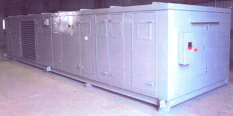
Packaged systems are primarily associated with single-duct systems. They can be "off-the-shelf" or custom built, and can have many HVAC-system components and configurations. Cooling components can include compressors, condensers, and evaporators. (These can also provide heating if configured for operation as a heat pump). Separate primary heating components may include a gas furnace or electric resistance coils.

Rooftop air handler (RTAH)
Built-up Systems
Built-up systems tend to be physically larger than packaged systems, assembled onsite from individual components. They typically contain a cooling coil using chilled water from a central chiller plant. Heating, if provided, is supplied by hot water or steam coils, usually from a central hot-water or steam boiler. Some older units have staged electric resistance heat. Built-up systems contain at least one supply fan for moving the air through the dampers, air filters, and coils, into the duct system.
For air-handling systems that recirculate some of the supply air (this applies to many large package units as well), a return-air fan moves the air from the conditioned space back to the air handler. For air-handling systems equipped with an economizer, a relief-air path is provided to allow the extra outdoor air introduced by the economizer to exit the building and prevent problems controlling building pressure.
Key Components of Air Distribution Systems
The key components of air distribution systems are:
- Fans
- Coils
- Filters
- Dampers
- Ducts
Fans
Fans move air by pushing it with impellers (blades) powered by a motor. Pushing the air increases pressure which is measured in inches of water.
As the air is pressurized, it is heated by friction as it passes through the fan. More heat is added if the fan motor is located in the air stream. The air temperature can rise from 1 to 5 or more degrees, depending on the system operating pressure.
The most common fan designs used in HVAC systems are centrifugal and axial.
Centrifugal
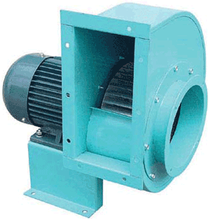
With centrifugal fans, air enters the fan housing through the rotor, makes a 90° turn, is captured by the scroll-shaped housing and fan blades, and forced through the fan discharge. Three types of centrifugal fans are common in HVAC applications:
- Airfoil: Fans with backward-curved fans and deep airfoil blades. These are the most efficient centrifugal fans and rotate at higher speeds.
- Backward curved: Fans with flat wheel blades that lean away from the direction the fan is turning. This design is only slightly less efficient than the airfoil design.
- Forward curved: Fans using small blades that are curved forward in the direction of the rotation. These are the least efficient of the three centrifugal designs and are used mainly in low-pressure HVAC applications.

Centrifugal fan
Axial
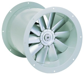
With axial fans, air moves in a straight path through the propeller-type rotors to produce airflow. Three types of axial fans are common in HVAC applications:
Vane axial: Fans with fixed, adjustable, or controllable-pitch blades. These are the most efficient axial fans. Guide vanes in front of or behind the fan blades increase pressure capability and efficiency. These are direct-drive units without fan belts. Vane axial fans are noisy and usually require sound attenuation.
Tube axial: Fans typically used where space constraints prohibit use of a centrifugal fan.
Propeller: Fans typically used to move large volumes of air at a low increase in pressure. These are the least efficient fan design.

Axial fan
Coils
Coils are heat exchangers that transfer energy between the supply-air stream and the energy-transport medium: water, steam, or refrigerant.
Most coils are made of copper tubing arranged in rows, specifically designed for the amount of energy transfer required. They may be bare tubes when differential temperatures are high, or have extended fins where differential temperatures are lower.
Generally, to transfer more energy per cubic foot of air, more rows and fins are required. Adding rows makes the coil "deeper" and increases the static pressure loss across the coil.
Filters
Air filters are used to prevent airborne particulates from entering and recirculating within a building, and to protect fans, coils, other downstream equipment and the occupants. Most contaminants in the air stream are generated internally from occupants by items such as clothing, paper dust, and copier toner. External contaminants also contribute particulates to the indoor environment. For instance, engine exhaust contains a fine soot-like substance. Filters have various levels of filtration and are classified by ASHRAE Standard 52.2 by MERV (Minimum Efficiency Reporting Value).
Most air handlers are sized to move air at 300-600 fpm through the filter section. Higher velocities cause particulates to blow through the filters, reducing their effectiveness. Airflow through all filter banks should therefore be as uniform as possible to avoid creating areas of high velocity characteristic of turbulent airflow.
There are three general types of filters:
- Fibrous medium panel: The filter medium has a viscous surface and particulates strike the medium and stick. These range from the old standard of 30% (MERV 4) to 99.99% HEPA filters (MERV 15 and up). Sizes vary from 12" square to 24" square.
- Renewable fibrous roll filters: These filters typically use MERV 4 filter material on rolls. A differential-pressure sensor activates a small motor that rolls the filter across the air stream in the air handler. This action does not replace the filter across the entire air stream but only enough to lower the pressure drop back to an acceptable level. This creates a low (less than design) velocity in the dirty portion and a higher (above the design) velocity through the clean portion.
- Electronic air cleaners: These use electronic precipitation to filter the air. Particulates are positively charged as they pass through an ionization section. These positively charged particulates then pass through a collection section with positively DC-charged plates. The particulates are attracted to the plates and adhere. These air cleaners produce ozone, though rarely in concentrations that is a health hazard, when properly maintained.
Dampers
Dampers direct and control airflow through the air distribution system. They can also be installed in certain fire-rated walls or floors for life-safety to prevent the migration of fire and smoke. These motorized units are typically controlled by the fire-alarm system but recent advances in the reliability of direct-digital-control (DDC) systems have allowed the HVAC DDC system to also control life-safety systems.
Dampers are classified by blade arrangement, leakage rate, and control type.
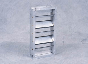
Blade arrangement (parallel or opposed-blade): Airflow through a parallel-blade damper is not linear with respect to the damper position. Ninety percent of the design flow-rate can be reached with the damper at 50% open. An opposed-blade damper is much more linear, allowing for more precise control through the entire travel of the actuator.
A variant of the parallel-blade damper is the back-draft damper. This typically operates by air pressure and is designed to allow air movement only in one direction, such as from building exhaust systems. These are not low-leakage dampers and can allow air to escape from a building under certain conditions, even when the fan is off.

Opposed-blade damper (Ruskin)
Leakage rate: This typically specifies the quality of the construction: a lower leakage rate indicates a higher-quality damper. Many energy codes now require "low-leakage" dampers in outside-air applications for energy conservation.
Control type (modulation or two-position): Modulation dampers have actuators that respond to a variable input from the DDC system and control airflow, typically between minimum and maximum positions. These are used in VAV terminal units as well as air-side economizers in air handlers.
Two-position dampers have actuators that either fully open or fully close the damper. They are used for isolating exhaust fans from the exterior when not running. They are also used extensively in life-safety applications for fire dampers and fire/smoke dampers.
Ducts
There are two general types of duct systems: single-duct and dual-duct. Each type can be used in both constant- and variable-flow applications.
Ducts are usually made of galvanized steel and are commonly wrapped or lined with fiberglass thermal insulation, both to reduce heat loss or gain through the duct walls and to prevent water vapor from condensing on the exterior of the duct when the duct is carrying cooled air. Insulation, particularly duct liner, also reduces duct-borne noise. Both types of insulation reduce "breakout" noise through the duct walls.
While galvanized steel is the most common material, ducts can be manufactured from duct board, a rigid form of fiberglass. The fiberglass provides built-in thermal insulation and the interior surface absorbs sound, helping to quiet the operation of the HVAC system. This type of ducting is typically used in low-pressure systems, 2" wg or less, due to the structural limitations of the material.
Flexible ducts, also called "flex," have a variety of material configurations, but are typically flexible plastic over a metal wire coil to make round, flexible duct. Most often, a layer of fiberglass insulation covers the duct, and a thin plastic layer protects the insulation. Flexible duct is convenient for attaching supply-air outlets to the rigid ductwork. However, the pressure loss through flex is higher than for most other types of ducts. As such, duct runs should be short, less than about 15 feet, and as straight as possible. Kinks in flex must be avoided. The most common use of flex is to connect ducted supply air to terminal units.
Regardless of the material, sealing ducts properly is critical to prevent unavoidable leakage.
Safety Issues
Before servicing fans and associated equipment, disconnect the power supply to the motor and accessories. Working near any operating rotating equipment is potentially hazardous. Electronic filters may require special grounding before they can be safely serviced. Always consult manufacturers' equipment manuals for safe maintenance practices and observe lockout/tag-out protocols.
Best Practices and Indicators of Efficient Operation
These best practices will help improve the performance of air-distribution systems and reduce operating costs:
Improve control of dry-bulb-temperature economizer: An economizer is designed to reduce or eliminate mechanical cooling when the outside-air temperature is lower than the return-air temperature. Frequently, economizer change-over setpoints are too low to take advantage of the maximum economizer cooling hours available. Economizers can save considerable energy but are often underperforming without the knowledge of the building operators.
Energy-efficient control strategies:
- Scheduling the air-handler system: Check equipment scheduling in the DDC system or mechanical time clocks. Equipment schedules are often "temporarily" expanded, then forgotten.
- Reset supply-air temperature: Moderate weather, typically in spring and fall, permits a warmer supply-air setpoint for cooling and a cooler supply-air setpoint for heating.
- Widen zone-temperature dead bands: This will minimize energy use and help prevent unnecessary "fighting" between the heating and cooling systems. It also controls instability characterized by short-term cycling between heating and cooling modes.
- Close outside-air dampers during morning warm-up in heating season. While warming the building before the occupants arrive, make sure the outside-air dampers are fully closed.
- Perform early-morning flush: In cooling season, precool the building with 100% outside air (when the outside-air temperatures permit) before starting mechanical cooling.
- Employ optimum-start control: Many building DDC systems have an optimum-start control feature which, when enabled, reduces energy use by starting the building HVAC system just far enough before occupancy to reach the occupied setpoint when the occupants arrive.
- Reset static pressure of VAV system: The static-pressure setpoint can be automatically reset through a zone-level control-feedback loop. This control strategy allows the supply fan to maintain the minimum airflow needed to maintain comfortable individual zone conditions.
- Turn off heating-coil valves in the cooling season: Many air-handler preheat coils and dual-duct hot-deck valves should be turned off in the cooling season to prevent incidental and unnecessary heating.
Best Practices for Maintenance
Here are some suggestions for improving maintenance practices by component:
Filters: All filters are not created equal. Upgrade existing filtration systems with extended-surface-area filters. These filters have a lower initial pressure drop, higher dust-holding capability, and higher structural ratings. Benefits include longer change cycles and lower pressure drops (which conserve fan energy).
Filters are sometimes changed at a regular time interval, before the end of their useful service life. Follow filter-manufacturer guidelines and use pressure drop across the filter bank as the criterion for changing filters.
Fans: Fans typically provide years of trouble-free operation with relatively minimal maintenance. However, this high reliability can lead to complacency, resulting in neglected maintenance and eventual failure. Follow established preventive-maintenance protocols for cleaning housings and fan blades, lubricating and checking seals, adjusting belts, checking bearings and structural members, and tracking vibration.
Coils: Coil cleanliness directly effects the efficiency of heat transfer to and from the air stream, and the performance of the entire HVAC system. A clean coil has a lower water-side and air-side pressure drop, and thus lowers fan and pump energy consumption. Lower fan and pump energy consumption also means reduced fan and pump heat - a parasitic load for cooling processes. Cleaning dirty coils is often deferred because it is unpleasant and time-consuming. The best coil-cleaning strategy is to prevent them from becoming dirty in the first place with regular filter maintenance (coil exterior) and water treatment (coil interior).
Sensors: Clean and calibrate sensors. Trying to control an HVAC system based on false input values from miscalibrated sensors is futile. Similarly, a clean and calibrated sensor in a bad location will defeat an otherwise well-executed control strategy.
Ducts: Duct leakage can prevent a large percentage of supply air from reaching the intended destination. Routinely check ductwork and access ports for leakage and insulation integrity. Flex ducts near terminal units may become disconnected or crimped, greatly reducing airflow to the terminal unit.
Vibration analysis: A good predictive-maintenance practice is the periodic use of vibration analysis on large fans and motors. Vibration signatures are compared with previous readings for indications of component degradation such as worn bearings, shaft alignment, or fan-blade imbalance. It may be economical in large facilities to buy the equipment and train an in-house engineer to perform this analysis. Otherwise, hire an outside contractor.
The table below provides a checklist for maintenance tasks.
References
Colen, Harold R. 1990. HVAC Systems Evaluation, Kingston, MA: R.S. Means Company, Inc.
ASHRAE Handbook 2000, Heating, Ventilating and Air-Conditioning Systems and Equipment, Atlanta, GA, American Society of Heating, Refrigerating and Air-Conditioning Engineers, Inc.
Pacific Gas and Electric Company 1997, Central HVAC Systems and Applications in Commercial Facilities, Pacific Gas and Electric Company.
FEMP O&M Best Practices Guide 2.0, July 2004
FEMP Continuous Commissioning Guidebook for Federal Energy Managers, October 2002
Healthcare Energy Guidebook, American Society for Healthcare Engineering, December 2003.
Building Performance Services, Northwest Energy Efficiency Alliance, 2003.
